Prairie River Bridge | Truss Attachment
Jan 14, 2023
Introduction
In my previous post of the Prairie River Bridge series, I had finished the assembly of the floor beams and stringers. Now that the major subassemblies are ready, including the three trusses that were assembled earlier, I will be attaching the trusses to the floor beams and adding the floor beam braces. The internal bracing will be added later, after everything has been fastened together.
Center Truss
History
The Prairie River Bridge was built in 1899 and the center truss was added in 1929 when heavier locomotives came into service. They would have constructed the truss through the existing framework while the bridge was still in service. The truss sits three feet below the floor beams and the support pillars transfer the load from the bottom of the floor beams to the top of the truss. Adding a third truss line to deck truss bridges was apparently a typical strengthening project for bridges built by the Great Northern in the late 1800s.
Preparation
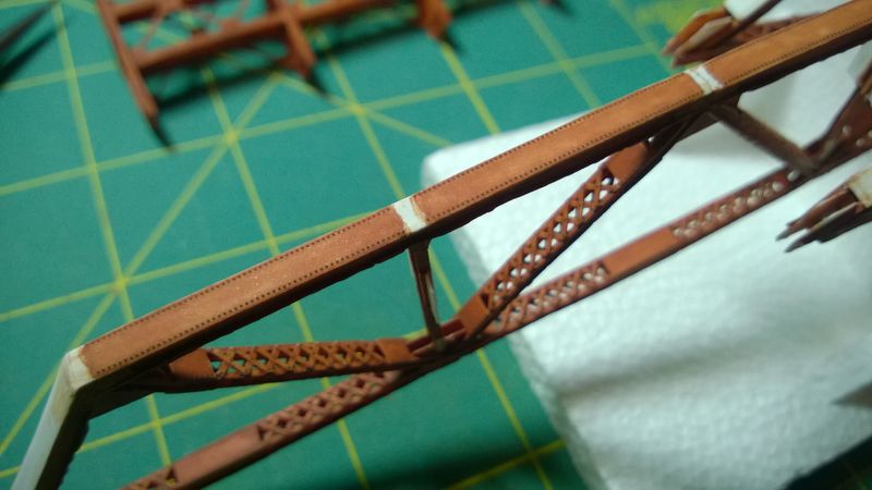
Strips of Archer Fine Transfers N Scale Resin Rivet decals are applied to the top of the center truss followed by several thin layers of DecoArt Americana Burnt Sienna acrylic flat base coat as shown in Figure 1. Once the trusses are attached, the floor beams will protect the rivet decals from damage. The unpainted gaps are where the floor beams will be attached at the tops of the diagonals and verticals. These don't have to be accurate paint edges since they will be touched up after the truss is attached.
Assembly
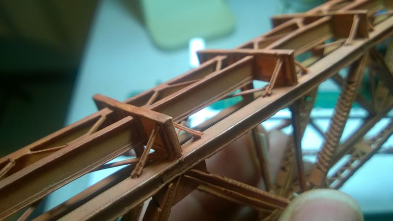
The top of the center truss is attached to the support pillars in the middle of the floor beams. The center of the diagonals and verticals should be aligned with the support pillars and the truss should be perpendicular to the floor beams. It does not have to be perfectly perpendicular since the sway braces will keep everything in line later. Several thin layers of base coat are applied to touch up the connection points as shown in Figure 2.
Outer Trusses
Connector Plates
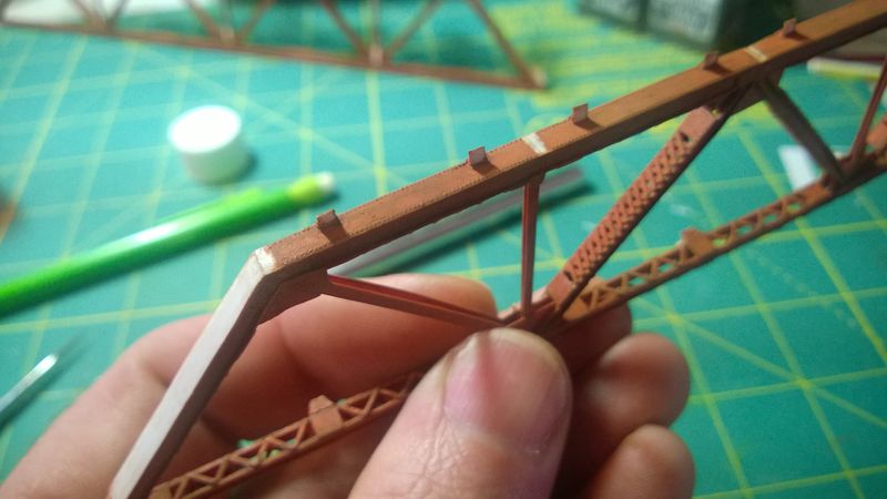
Connector plates are needed for the bottoms of the floor beam braces. The connector plates are scale 16"x16" squares cut from a scrap of 0.010" styrene sheet from Evergreen Scale Models. 0.030" angle iron is fabricated from 0.010" styrene strips and cut into scale 16" lengths to support the connector plates. These are then attached to the tops of the trusses, four scale feet from the floor beam centers. The connector plates are then attached to the sides of the angle irons as shown in Figure 3.
Preparation
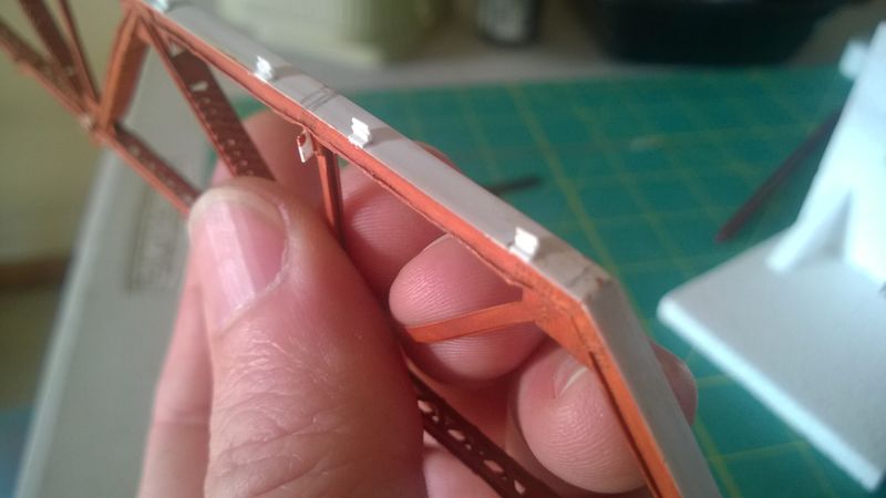
Strips of rivet decals are applied to the tops of the trusses followed by several thin layers of base coat as shown in Figure 4. Similar to the center truss, the unpainted gaps are where the floor beams will be attached. The fronts of the connector plates are also left unpainted for the floor beam braces that will be attached later.
Assembly
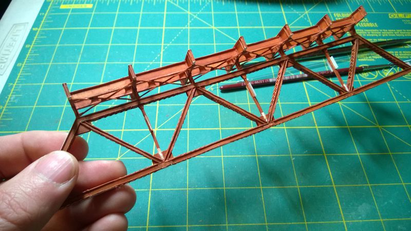
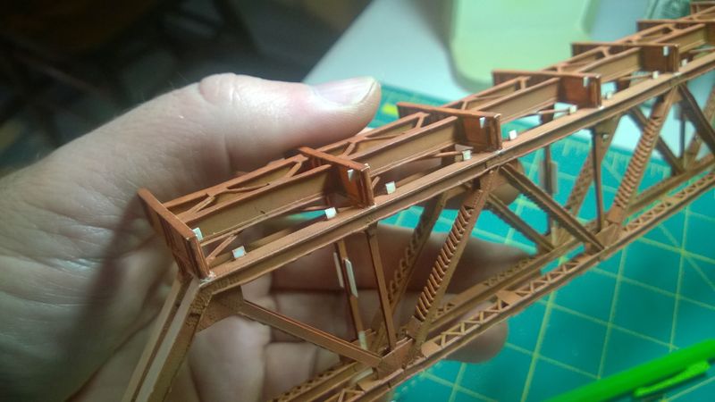
The outer trusses are attached to the bottom ends of the floor beams as shown in Figure 5. The floor beams should align with the center of the supporting diagonals and verticals. All three trusses should be perpendicular to the floor beams and parallel to each other. Connector plates for the tops of the floor beam braces are also mounted to the side of the second stiffener on the tops of the floor beams after scraping away a bit of paint. These should line up with the other connector plates so that both ends of the floor beam braces have a flat mounting surface.
Floor Beam Braces
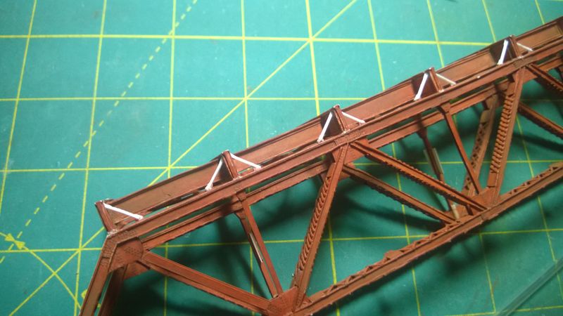
0.030" angle iron is fabricated from 0.010" styrene strips and cut into scale 4' 6" lengths for the floor beam braces. These are attached to the fronts of the connector plates to brace the tops of the floor beam ends and prevent them from moving sideways. The floor beams should be perpendicular to the top of the truss before attaching the braces. After the braces are attached, the corners of the connector plates are trimmed off a shown in Figure 6.
Conclusion
I gave the floor beam connector plates and braces several thin layers of base coat as shown in Figure 7 and touched up a few spots where paint had either worn or chipped off during handling. Everything should still be a bit wobbly. Now that the trusses are attached to the floor beams and the floor beam braces are installed, check out my next post of the Prairie River Bridge series where I take care of that by installing the internal braces!
